EXPERIMENT No. 2
DIODES

Fig 3 - Diode Symbol & Physical component


Fig 4 – Diode symbol and P.N. junction
A diode has the characteristics of:
· An insulator when current tries to flow in one direction.
· A conductor when current flows in the other direction.
Components: 1 x diode, 1 x LED
Exercise: Using a multimeter, identify the anode and cathode of the diode and the LED.
Voltage drop in forward Biased Direction. | Voltage drop in reverse biased direction | |
LED | 1.784v | 0v |
Diode | 0.568v | 0v |
Explain how you could identify the cathode without a multimeter
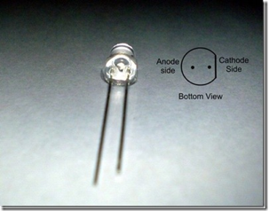
To identify the cathode side of a LED without a multimeter look on one side and it should be flat. The flat side identifies the cathode. This is a good way to identify the cathode side because the leads could be cut. The anode lead is longer than the cathode. Below is picture I saved of the internet showing an LED and its flat side.
(Refference) http://elecrom.wordpress.com/2008/03/02/anode-and-cathode-of-led/
On a normal Diode the grey band represents the cathode side. The anode lead is longer than the cathode. Below is a picture showing a diode and its grey band showing the cathode side.

(Reference) http://camhardyreidttec4841.blogspot.com/2011/05/diodes.html
Table 1: Data sheet of 1N4007 is as follows
Absolute Maximum Ratings, TA = 25OC | |||
Symbol | Parameter | Value | Units |
IO | Average rectified current @ TA = 75oC | 1.0 | A |
PD | Total device dissipation Derate above 25oC | 2.5 20 | W mW/OC |
Thermal resistance, Junction to Ambient | 50 | OC/W | |
Storage Temperature Range | -55 to + 175 | OC | |
Operating Temperature Range | -55 to + 150 | OC | |
VRRM (PIV) | Peak repetitive reverse voltage | 1000 | V |
Components: 1 x resistor, 1 x diode. 1 x LED
Exercise: For Vs=5V, R= 1KΩ, D= 1N4007 build the following circuit on a breadboard.

Fig 5
Calculate first the value of current flowing through the diode, now measure and check your answer?
Show your working
Calculated Measured
I = V/R = 5 – 0.6 = 4.4/1000W = 4.4mA 4.4mA
Is the reading as you expected; explain why or why not?
The reading is as I expected because I calculated the current using ohms law and then I measured the current flow with a meter and compared answers.
Calculate the voltage drop across the diode, now measure and check your answer?
Calculated Measured
V = I X R = 4.4 X 1000 = 4.4mA 0.6VD
VD = Vs – V1 = 5 – 4.4 = 0.6v
Using the data sheet given in Table 1 above,
What is the maximum value of the current that can flow through the given diode?
The average rectified current that can flow through the given diode is 1.0A @ 75°C
For R = 1KΩ. What is the maximum value of Vs so that the diode operates in a safe region?
The maximum value of Vs so that the diode operates in a safe region is 1000 V.
Replace the diode by an LED & calculate the current, then measure and check your answer?
Calculated Measured
I = V/R = 5 – 1.8 = 3.2 / 1000 = 0.0032A 3.2mA
What do you observe? Explain briefly.
Looking at the LED and Diode, the LED requires a higher potential difference to move electrons through the boundary layer and turn it on than the Diode. electric charge flows through the Diode at a less voltage to open the gate therefore more electrons can flow freely.
No comments:
Post a Comment